
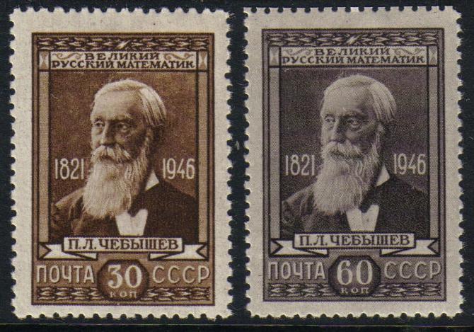
On the occasion of the 200th year of Pafnuty Lvovich Chebyshev’s birth, we survey his works on mechanical linkages. Let us first explain the main object considered in this paper. A mechanical linkage is a set of rigid bars connected with each other at the ends by revolving hinges. This construction can move and bend in the hinges and take different configurations. A natural example of a linkage is an arm of a human or a leg of an animal with its bones as bars and joints as links. The main purpose of linkages is to produce different kinds of motions, and humankind has been using them in engineering since antiquity.
Chebyshev was interested in mechanics from a young age, but his research in this field started only after a voyage to Europe which he undertook in June–October 1852. It was a scientific trip sponsored by the Saint Petersburg Academy of Sciences. During this journey, Chebyshev established connections with famous European mathematicians and, alongside with his theoretical research, observed factories and workshops, learning about the latest achievements in engineering and machinery. After his return, in the period 1852–1856, he gave lectures on applied mechanics at the Alexandrovsky Imperial Lyceum, in addition to his work at the University of Saint Petersburg.
- The theory of the mechanisms known under the name “parallelograms”, 1854 [3][I, pp. 539-568];
- On the modification of Watt’s parallelogram, 1861 [3][I, pp. 433–438];
- On a mechanism, 1868 [3][II, pp. 51–57];
- On the parallelograms, 1869 [3][II, pp. 85–106];
- On the simplest parallelograms that are symmetrical with respect to an axis, presented in a congress of Association fran\c caise pour l’avancement des sciences in 1878, published in 1885 [3][II, pp. 709–714];
- The simplest systems of linked bars, 1878 [3][II, pp. 273–281];
- On the parallelograms that are constructed from three elements and are symmetrical with respect to an axis, 1879 [3][II, pp. 285–297];
- On the parallelograms that are constructed from three elements, 1879 [3][II, pp. 301–331];
- On the simplest parallelograms that deliver the rectilinear motion up to the fourth order, 1881 [3][II, pp. 359–374];
- A theorem related to Watt’s curve, 1881 [3][II, p. 715];
- On the transformation of the circular motion into a motion alongside certain lines with the aid of linked systems, 1884 [3][II, pp. 726–732];
- On the transformation of the circular motion into a motion alongside certain lines with the aid of linked systems, 1884 [3][II, pp. 726–732];
- On the transformation of the circular motion into a motion alongside certain lines with the aid of linked systems, 1884 [3][II, pp. 726–732];
- On the transformation of the circular motion into a motion alongside certain lines with the aid of linked systems, 1884 [3][II, pp. 726–732];
- On the simplest linked system that delivers motions symmetrical with respect to an axis, 1889 [3][II, pp. 495–540].
These works can be considered as multiple parts of one long line of research. The word “parallelogram” that appears in several titles of these papers was first used to denote a specific mechanism, namely, Watt’s parallelogram, and its improvements. In later works, it was used by Chebyshev to denote linkages somehow related to this mechanism. The titles of the papers have a mechanical connotation, but the content of most of them is purely mathematical. It is worthwhile to say that Chebyshev used linkages to develop the theory of approximations of functions.
The bars of a linkage are related via algebraic relations between the coordinates of the links or chosen points on the bars. Therefore, if the position of some points of the linkage on the plane are fixed, then the trajectories of the other moving points are algebraic curves. The natural questions that arise here are: What kind of algebraic curves can be obtained by these motions? What curves on the plane can be approximated by the curves traced out by chosen points on the linkages? Although Chebyshev turned his attention to the general theory of approximations, these questions remained important. William Thurston and Nikolai Mnev turned the gaze back to these questions in the last quarter of the 20th century, resulting in proving a series of universality theorems for linkages. For an exposition of the modern history of this question see~[2].
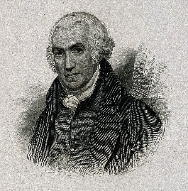
Now we shall say a few words about Watt, since Chebyshev refers to him in several of his papers. James Watt (1736–1819) was a Scottish engineer, and one of the pioneers of the Industrial Revolution. One of his famous inventions was an improvement of the steam engine (the first steam engine invented by Thomas Newcomen was extremely inefficient). Watt’s name is also used to denote a SI unit of power.
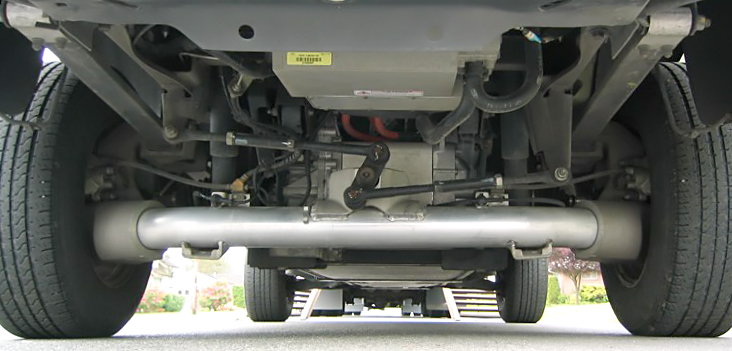
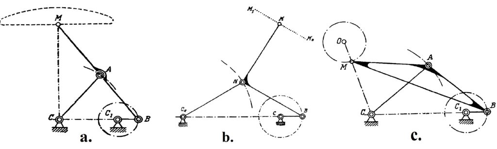
It consists of three bars linked in a chain with the positions of the two ends of this chain fixed. The two bars on the sides can rock around the fixed points at some degrees and the trajectories of the nodes D and F are segments of circles. Every point M on the middle bar has a specific trajectory, which is called Watt’s curve and can be defined with an equation of degree six. If the rockers are of the same length and the point M is in the middle of the bar DF, then a certain segment of the trajectory of the point M approximates a straight line, and this approximation is the goal of this whole construction. This linkage remains in use today, for example, in some car suspensions to prevent relative sideways motions between the axle and the body of the car (Fig. 5).
 |
 |
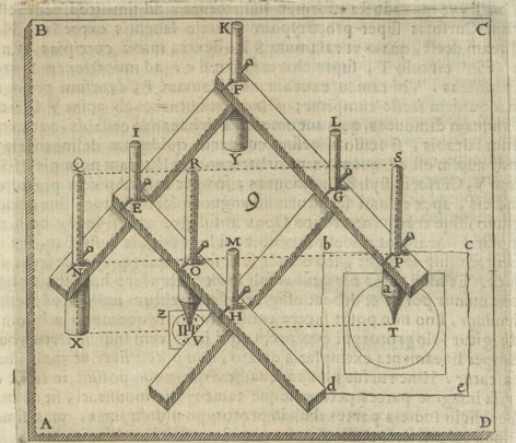
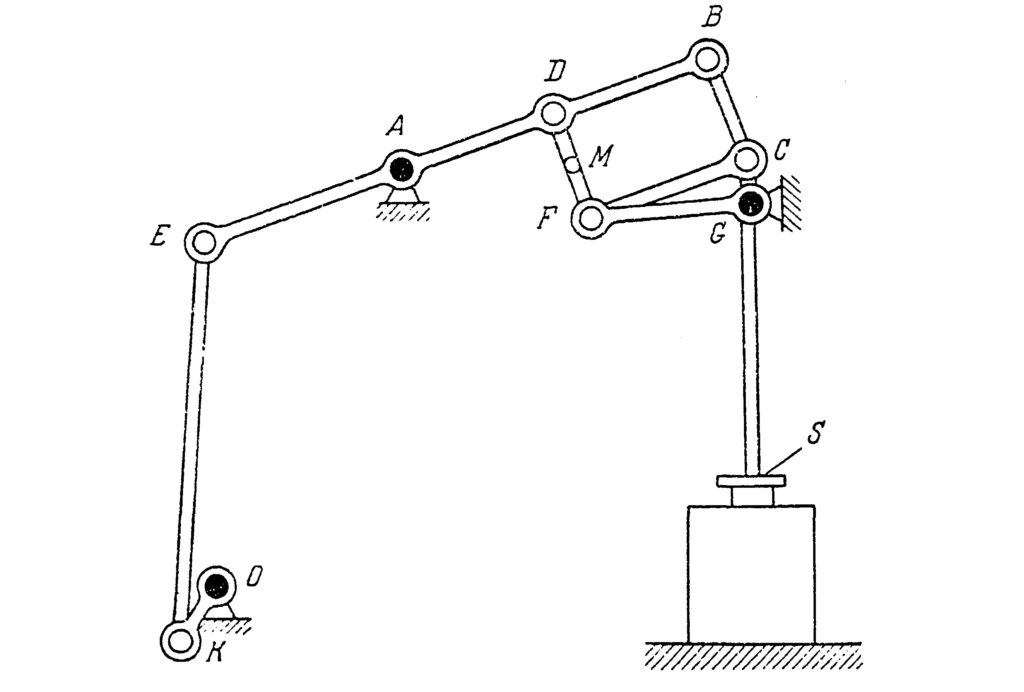
Watt’s parallelogram is obtained by combining Watt’s linkage with a pantograph (a parallelogram). It was used in steam engines to translate circular motion into rectilinear. The full mechanism is shown in Fig. 6, where Watt’s parallelogram is the upper part of it. The machine transforms the circular motion of the point K through the rocking of the points E and B into an almost rectilinear motion of the points M and C, which enables a truly rectilinear motion of the piston S, but with some side tension. Chebyshev wrote about this mechanism in his report on the journey of 1852 [3][II pp. VII–XIX]. He noted a lack of underlying theory for this invention, which led to certain problems for its improvement and alterations. Such alterations and improvements were needed for two reasons.
The first work in the preceding list is a 25-page paper where Chebyshev developed a theoretical foundation for solving problems such as finding the optimal proportions for Watt’s mechanism. He reformulated the question in purely mathematical terms, and stated a much more general problem:
This was the starting point of a new mathematical school of the approximation of functions, which led to results far beyond purely mechanical questions.
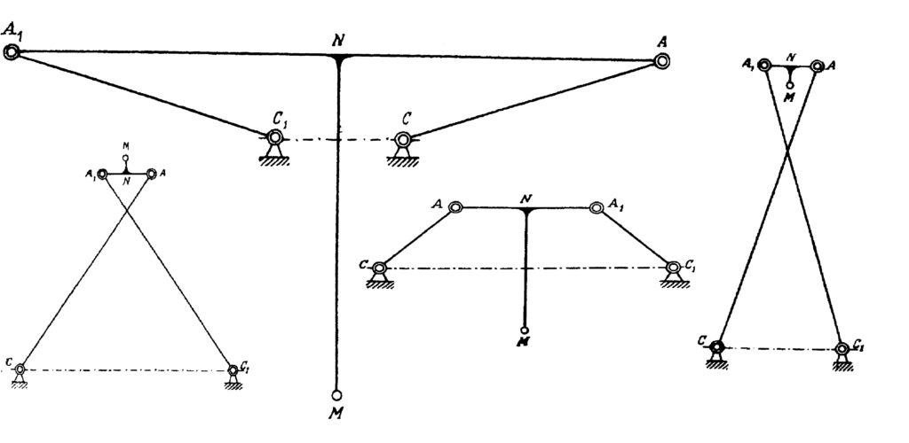
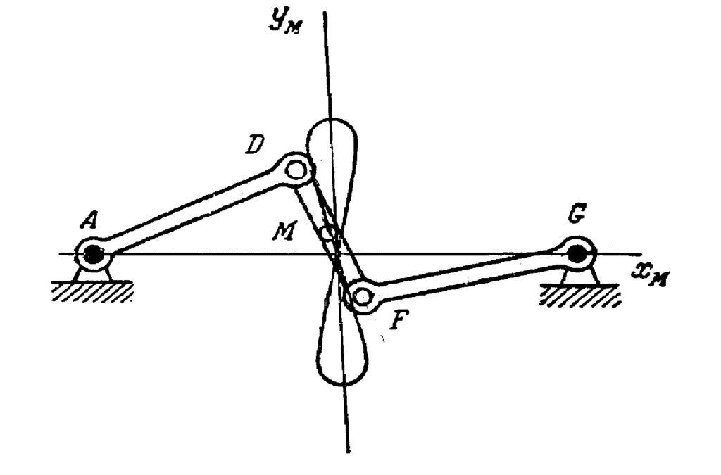
The one-page note (Paper 10) gives a theoretical boundary for the precision of the movement delivered by Watt’s mechanism. The paper 11 discusses three mechanisms shown in Fig. 10 that were invented by Chebyshev. We have already talked about the first two of them, which appeared in the paper 6, so now we shall comment on the last one. It is the four-bar reversing mechanism. The trajectory of the point M here is almost circular and the direction of its circular motion is opposite to the direction of the point B.
 |
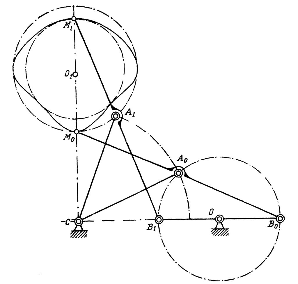 |
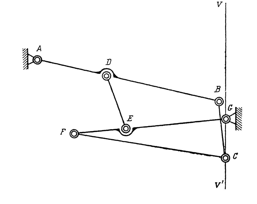
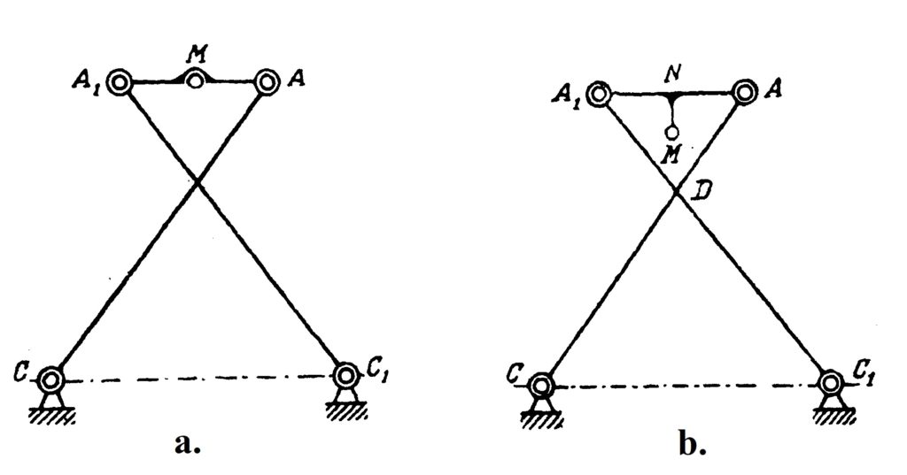
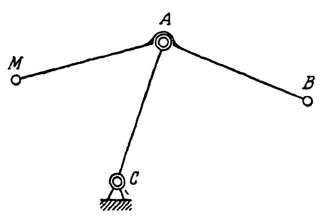
In the last paper of our list, Chebyshev studied the possibilities of the simple system represented in Fig. 11. The point B is a hinge, but the angle MAB is fixed. All three mechanisms in Fig. 10 contain such a system, but with different values of this angle. This system transforms a motion of the point B into a motion of the point M, and Chebyshev in this paper studied various possibilities of such a transformation. For example, if you change the radius of the circulation of the point B in the lambda-mechanism, which incidentally should be exactly \frac{|AB|}{5}, you will get a completely different trajectory of the point M, see Fig. 12. This example shows the importance of the exact proportions of the linkages. Although the linkage in Fig. 12 has a nice property—that the trajectory of the point M lies strictly between two concentric circles—it circulates in a direction opposite to the direction of the circulation of the point A. This linkage is the basis for another of Chebyshev’s inventions, the “six-bar reversing mechanism”.
We have surveyed the almost 40-year work of Chebyshev in inventing and analysing mechanical linkages. This is only a part of his work; it does not reflect the whole gamut of his scientific interests, which was very broad. This research can serve as an illustration of how theory and practice support and develop each other. This synergy was one of the driving principles of Chebyshev’s work; it showed how unsolved practical questions can give rise to new perspectives in completely different fields of mathematics.
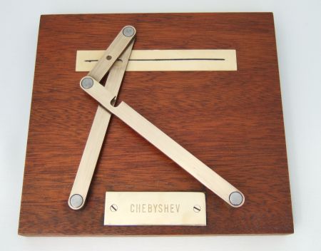
On the basis of the linkages described in these papers, several other inventions were made by Chebyshev. Models of mechanisms invented by him can be found in science museums in Russia, France and Great Britain. The animated versions of these machines can be found online on the site [5], created by Mathematical Etudes Foundation.\blacksquare
References
- A. Papadopoulos, Pafnuty Chebyshev (1821-1894), in this issue of Bhāvanā.
- A. B. Sossinsky, Configuration spaces of planar linkages, Handbook of Teichmüller Theory (VI), editor: A. Papadopoulos, IRMA Lectures in Mathematics and Theoretical Physics, European Mathematical Society, 2016, 335–374.
- P. L. Chebyshev, Works (French), edited by A. Markov and N. Sonin, Imprimerie de l’Académie Impériale des sciences, Saint Petersburg, 2 volumes, 1899–1907.
- G. de Prony, Sur le parallélogramme du balancier de la machine à feu, Annales de Chimie et de Physique, XIX; Annales des Mines, série 1, XII.
- Mechanisms by Tchebyshev, https://en.tcheb.ru/
Footnotes
- Charles-Nicolas Peaucellier (1832–1919), a French engineer. ↩
- Gaspard Clair François Marie Riche de Prony (1755–1839), a French mathematician and engineer, who worked mostly on hydraulics. ↩
| Letter from the director of the Conservatoire National des Arts et Métiers (National Conservatory of Arts and Crafts) to Chebyshev about the second model of the arithmometer and the donation of the model of slider-crank mechanism of the steam engine Nikolai Andreev, tcheb.ru | |